Brushroll speed control using motor current as a load proxy.
In some home vacuums, brushroll speed should change with floor type. Historically it’s been handled with expensive pressure sensors, a manual knob, or even a Bluetooth app (still my favorite example of an absurd product-user interaction: Bluetooth pairing to a running vacuum).
Insights
Pressure sensors work well, but even at high volumes they’re dollars each and can be a bit temperamental. Motor current sensing is cents. The “it’s just a fat resistor” kind of cheap. Most high-volume 32-bit microcontrollers already have solid ADCs, and low-side sensing (measuring current on the ground side of the motor) keeps the analog front-end simple.
Motor current as a proxy for mechanical load is the whole trick. On hard floors the brushroll load is minimal because the bristles often don’t even touch the floor. On thick “cashmere” carpets the loading is significant. The firmware reads that load off the motor current signal and pushes more duty cycle (voltage) to keep RPM from sagging.
Signal chain
The signal chain is tuned for BOM cost with a few small trade-offs. The main sensing element is a 1%-or-better 2W resistor. Some models add a general-purpose op-amp for a bit of gain. A low-pass RC filter does a first pass at noise attenuation before software filtering.
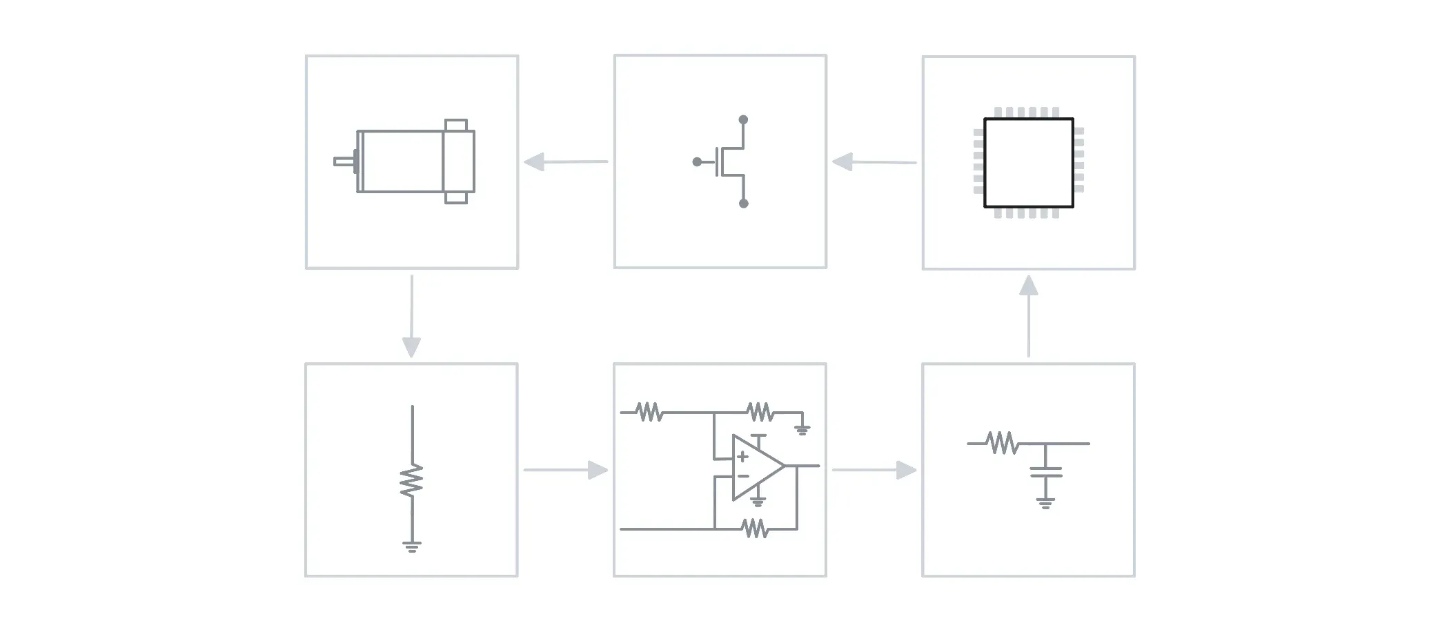
That hardware filtering matters because the whole scheme falls apart if it forces a beefier microcontroller. Jumping a tier up can get expensive fast. Letting the RC filter handle the worst-case noise means the software filter can stay light, which keeps the loop quick.
Control
My favorite part of this project, and ultimately why it’s on here, is how comedically elegant the control scheme ended up being, given how robust it was across carpet weights, speed modes, and load swings. There’s no PID, no elaborate motor model. Just a per-model current curve and some quick arithmetic.
The physics behind it is mostly straightforward. For a brushed DC motor, ignoring inductance at steady state:
V=IR+Keω
Where V is motor voltage, I is current, R is winding resistance, and ω is rotational speed.
When the brushroll encounters carpet, mechanical resistance increases. The motor slows, reducing back-EMF and allowing current to rise. Rearranging the equation for changes between operating points gives us:
KeΔω=ΔV−RΔI
This shows something really helpful. Increasing voltage by enough to offset the additional resistive drop maintains speed (IR compensation). Increase it further, and the brushroll can actually accelerate under load. Which is admittedly an odd feature, but for hard floor → carpet, it’s perfect.
The controller uses motor current as a proxy for that additional load. An empirically measured curve f(D), describes the expected no-load current at any PWM duty D.
The control approach is:
Dnext=Dbase+k(I−f(D))
Here, k is a gain that converts excess current into additional PWM duty cycle. The output is bounded by the allowed operating limits.
Different operating modes need different gains, tuned through testing in the lab. A low-speed setting needs more aggressive compensation than high speed, partly because the motor’s behavior changes across its operating range.
The entire approach really depends on the motor, product geometry, and electronics remaining sufficiently consistent between units.
Overcompensation
The interesting part comes from pushing the gain beyond what’s needed to maintain constant RPM.
At higher gain, the brushroll doesn’t just maintain speed on carpet, it actively speeds up in response to the load. One adjustment makes compensation a floor-responsive cleaning feature.
We spent a fair bit of time kicking this one around over coffee because this creates what looks like a potentially underdamped system. More carpet resistance → more current → more PWM → higher speed → more carpet resistance -> repeat… An unmanaged loop where it just slams to full speed and stays there.
Fortunately, that’s not the case. The reason becomes clearer when we look at what the controller is actually measuring.
We can approximate motor current as:
I=f(D)+q(D,L)
The first term, f(D), is the expected no-load current at the current duty cycle. The second, q(D,L), represents the additional current caused by loading, which can itself depends on speed and duty cycle.
Because the controller subtracts f(D), the expected current contribution cancels:
I−f(D)=q(D,L)
This is the important distinction. Increasing PWM will increase measured current, but the controller doesn’t interpret all of that increase as additional carpet loading. It only responds to current above what we’d expect at the new duty cycle of an unladen motor (plus belt, plus brushroll bearing friction, drag, etc.).
If the additional carpet load were completely independent of PWM, this would eliminate the reinforcing feedback entirely.Real carpet loading isn’t that simple, though. Increasing brushroll speed can increase mechanical resistance, so some positive feedback remains.
ΔDnext≈kβΔD
Here β describes how much additional excess current results from a small increase in PWM duty cycle. Importantly, for this controller corrections shrink rather than grow when:
∣kβ∣<1
For example, suppose an initial load causes a 10% PWM increase. The resulting additional carpet resistance might produce another 2% correction, followed by 0.4%, then 0.08%, and so on. The positive feedback is real, but each successive correction is smaller. The controller quickly converges to a new operating point rather than running away.
Of course, that’s a simplified picture. Motor inertia, electrical transients, filtering, and control-loop timing all affect the real stability. Excessively aggressive gains can still produce oscillations or saturation, and independent power limits provide an important safeguard.
What I find interesting is that the controller didn’t need a complicated dynamic model to achieve this behavior. By subtracting the expected no-load current, it rejected most of its own influence on the feedback signal, leaving an estimate of the mechanical load we actually wanted to respond to. This approach is a massive cost savings over more complicated pressure sensors at scale, e.g., $2/unit over 2 million units/year makes a tangible difference.
More
Once you have a current signal that can effectively ‘encode’ floor type, other aspects of the machine can be controlled. Suction is the obvious one:
- low current → hard floor → quieter suction
- high current → carpet → more suction
Whatever else in the machine wants or needs to know what surface is underneath can read the same signal.
I really love how the lowest-cost option, with a slight reframing, unlocked a bunch of doors for making the products more useful and enjoyable.